Visual algorithms and recognition and localization
Positioning guidance, defect detection, code reading, and measurement: a complete vision solution from light source selection to algorithm deployment.
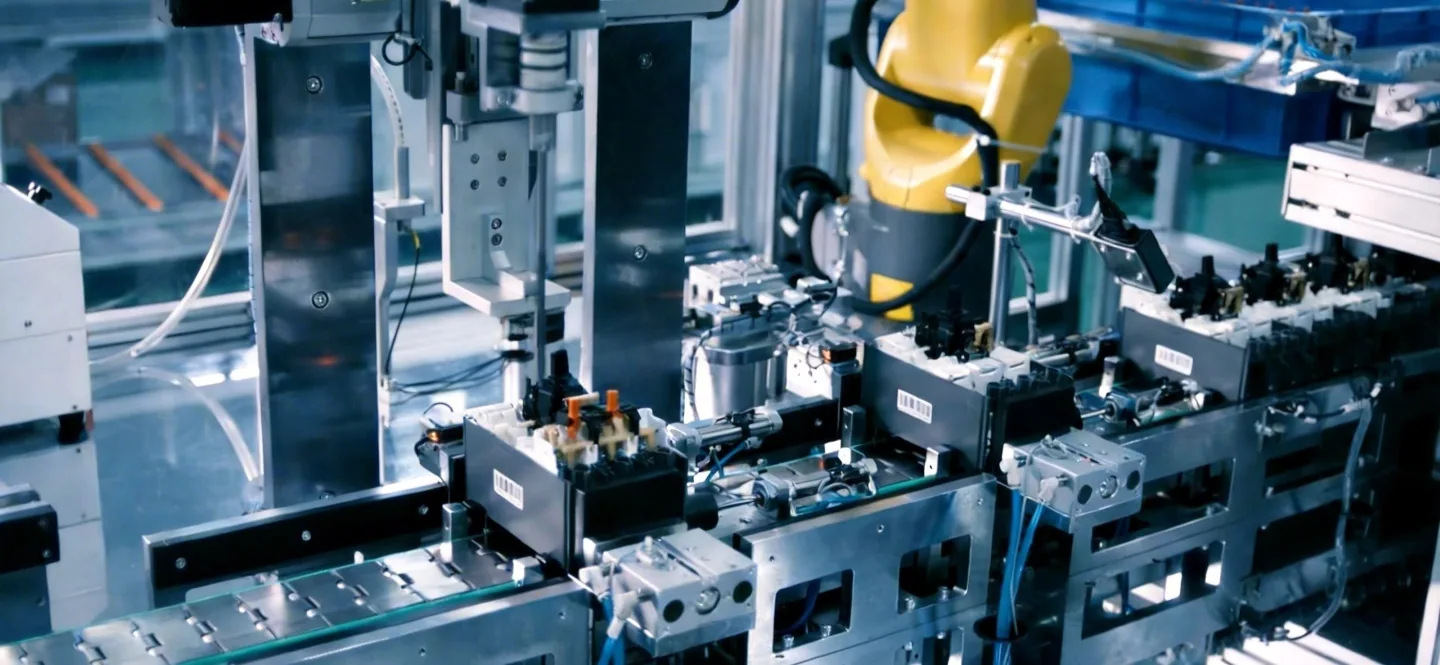
Most failures in vision projects are due to imaging rather than algorithms: if the light source is wrong, no matter how good the algorithm is, it can't be saved. We start with the imaging plan, first ensuring "clear shots," then proceed with algorithms and deployment.
Visual capability matrix
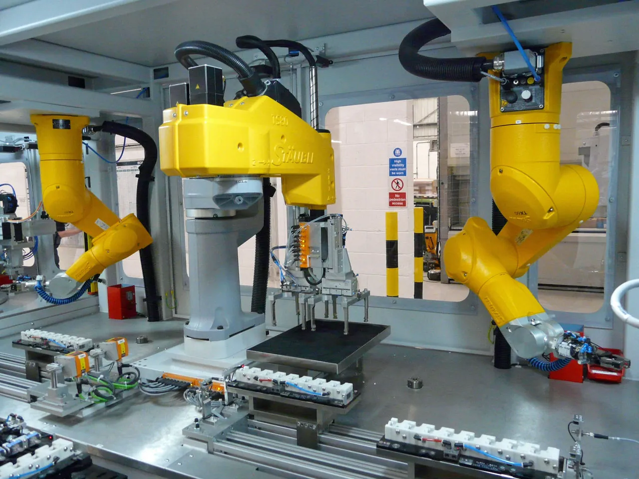
| Ability | Typical precision/indicators | Application scenarios |
|---|---|---|
| 2D positioning guidance | ± 0.1mm (field of view dependent) | Grasping and positioning, assembly alignment |
| 3D positioning | ±0.3mm | Random picking and stacking disassembly |
| Defect detection | Missed detection rate<0.5% | welds, surface scratches, missing parts |
| Code Traceability | Code reading rate> 99.9% | DPM code, tag code |
| Dimensional measurement | ±0.05mm | Online full size inspection |
Delivery process
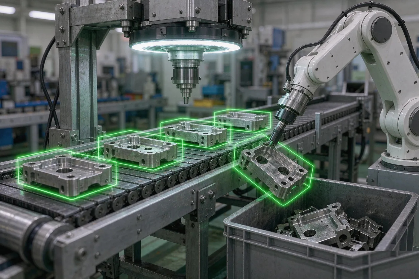
- 01Imaging solution validation (light source/camera/lens prototyping)
- 02Algorithm development and sample training
- 03Communication and deployment (robot/PLC integration)
- 04Acceptance of production line grayscale and indicators
Machine Vision: The four major functional levels that equip robots with "eyes."
Industrial vision is divided into four functional levels, with increasing complexity and value:Positioning guidance(Tell the robot where the workpiece is and what posture it is, to resolve disorderly picking and incoming material deviations),Measurement(Non-contact measurement of dimensional and geometric tolerances, subpixel algorithms up to ±0.01mm level),Testing(Defect detection: scratches, missing materials, misinstallation, character OCR, replacing human eye quality inspection)Identification classification(Automatically switches programs when mixing multiple product types).
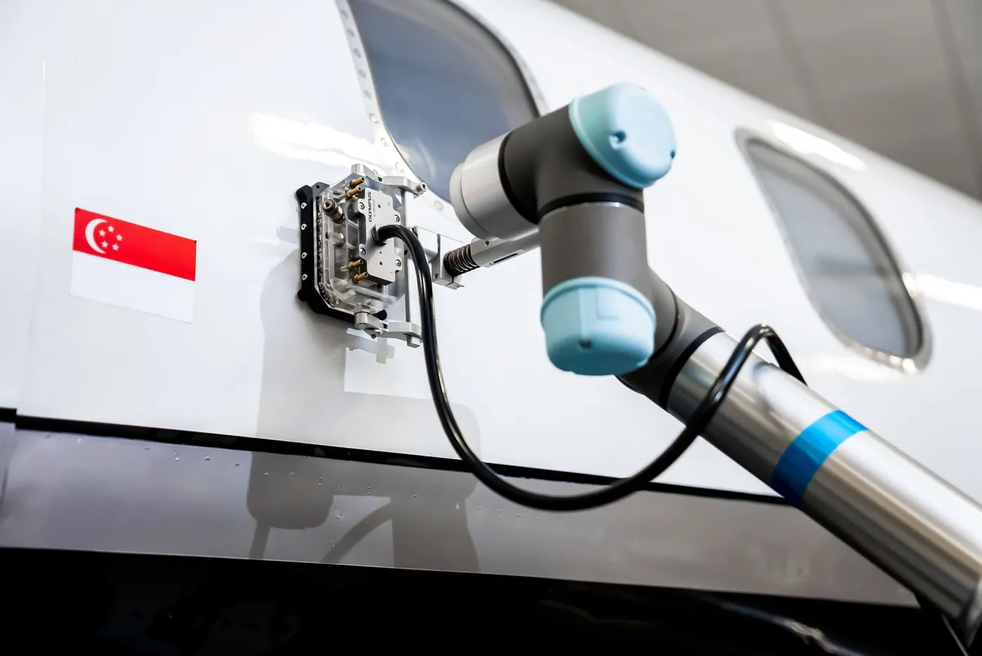
The current industry trend is the implementation of 3D vision and deep learning: 3D line laser/structured light solves the positioning challenges of reflectors and complex surfaces; Deep learning transforms defect detection—which is difficult to define rules (unusual colors, dirt, abnormal textures)—from undetectable to detectable, and can train usable models with hundreds of samples.
| Application requirements | Recommended plan | Key technical indicators | Typical Difficulties and Countermeasures |
|---|---|---|---|
| Positioning of planar workpieces | 2D vision + backlight/ring light | Positioning accuracy: ±0.05mm, processing time: <100ms | Polarizers for reflective components; Multi-workpiece use template matching + splitting |
| Random bulk material pickup | 3D vision + grasping planning algorithm | Point cloud registration accuracy: ±0.5mm, cycle time 1–3s | Layered recognition through stacked occlusion; Grip point collision verification |
| Appearance defect detection | Deep learning classification/segmentation models | Missed detection rate: <0.5%, overkill rate: <3% | Few defect samples are used for intensification with small samples; Lighting consistency is the prerequisite |
| Online measurement of dimensions | Telecentric lens + subpixel algorithm | Repeatability ± 0.005mm level | Temperature float calibration; Vibration isolation installation |
| Weld seam tracking | Laser vision sensors | Tracking accuracy: ±0.5mm, real-time capability: <20ms | Arc flash interference filtering; Groove feature extraction |
Vision project implementation process: optical verification comes first
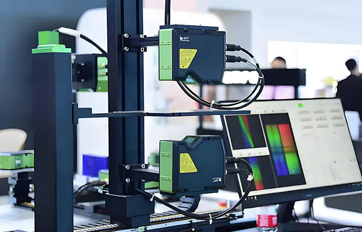
Step one: image feasibility verification.Conducting lighting tests using the client's actual products: light source type (ring/bar/coaxial/backlight/structured light), lens selection (telecentric/zoom/3D), installation distance and depth of field, and output image quality evaluation reports. If the image doesn't achieve stable features, everything that follows is empty talk—this step is not directly communicated by us about feasibility and alternatives.
Step two: Hand-eye calibration and precision closed-loop.Eye-in-Hand and Eye-to-Hand (Eyes on the Outside) are selected according to the working condition; Nine-point calibration + rotation center calibration; after calibration, use a measured mesh to verify positioning accuracy and issue an accuracy report.
Step three: algorithm development and beat optimization.Traditional algorithms (template matching, edge extraction, blob analysis) are prioritized—stable, fast, and interpretable; Deep learning only applies to defects where rules are difficult to define. Processing time is included in the overall station beat budget.
Step four: Production line joint commissioning and fault-tolerance design.Signal handshakes between vision and robots and PLCs, retake and rejection logic for failed recognition, alarm thresholds for light source attenuation—all are recorded in the interlock list.
In-depth Q&A
How many samples are needed for deep learning testing?
Qualified samples start at 200–500, with 30–100 defect samples per category. When defect samples are insufficient, defect synthesis and few-sample learning techniques can be used as supplements; For completely sampleless new products, it is recommended to first run traditional algorithm positioning + manual re-examination transition, then switch to deep models after accumulating data.
What should you do if the visual system breaks down the production line?
Design downgrade plans include automatic blind running mode (based on fixed points) or bypass manual workstations during visual failures, preventing detection from jamming the entire line. We provide annual maintenance of vision systems, including light source attenuation detection and model retraining services.
Can we add vision to our existing robots?
Yes. The vision system is independent of the robot brand and guides the robot via IO or bus communication. We have done communication integration with mainstream controllers from 21 brands; when older controllers do not support bus, we use IO handshake solutions.
Tell us your production line requirements
Process, cycle, budget, site conditions—the more specific you are, the more executable the plan. Local teams in Nanchong will be coordinated, and on-site inspections will be available in Sichuan, Chongqing, Yunnan, and Guizhou.
Contact usView all services